

Custom Video Wall Configurations: A Practical Planning Guide
What if the right video wall processor depends less on the number of screens than on what each screen needs to show? With custom video wall configurations, the image layout and content behavior should guide the system design. A wall that alternates between one full-screen image and several independent zones has different routing and control needs from a display that always acts as a single canvas.
Choosing hardware before defining the layout can create mismatches between sources, outputs, resolutions, and displays. Start by mapping the physical screen arrangement, listing what each area must show, and tracing how signals will reach the displays. These details turn an open-ended equipment decision into clear system requirements.
This guide explains how to translate a display layout into practical requirements, compare video wall processors with matrix switching approaches, and account for signal paths and control. You’ll also see where HDMI video wall processors and WolfPack Modular Matrix Switchers fit, so you can identify the right hardware category before comparing specific equipment.
Key Takeaways
- Define how the wall should display content, from one composed image to separate screen zones, before choosing processing hardware.
- Use a screen map to record display count, orientation, native resolution, and physical arrangement.
- Build an input-output schedule to clarify source devices, destinations, and switching needs for custom video wall configurations.
- Compare processors and matrix switchers by function: image composition across displays versus routing sources to selected outputs.
- Turn the finished requirements brief into a compatibility check for processing, routing, and control hardware.
What Custom Video Wall Configurations Need to Solve
A video wall is more than a set of panels mounted together. Custom video wall configurations bring the display arrangement, source devices, content, processing, signal distribution, and control together as one system. A Video wall may use LCD or LED displays, but the screens alone don’t determine how images are composed or routed.
Keep each component’s role clear. Display hardware produces the visible image. A video wall processor sizes, positions, or maps visual content across connected displays. A matrix switcher routes selected sources to selected outputs. Control provides commands for managing those functions, such as changing a source or selecting a layout.
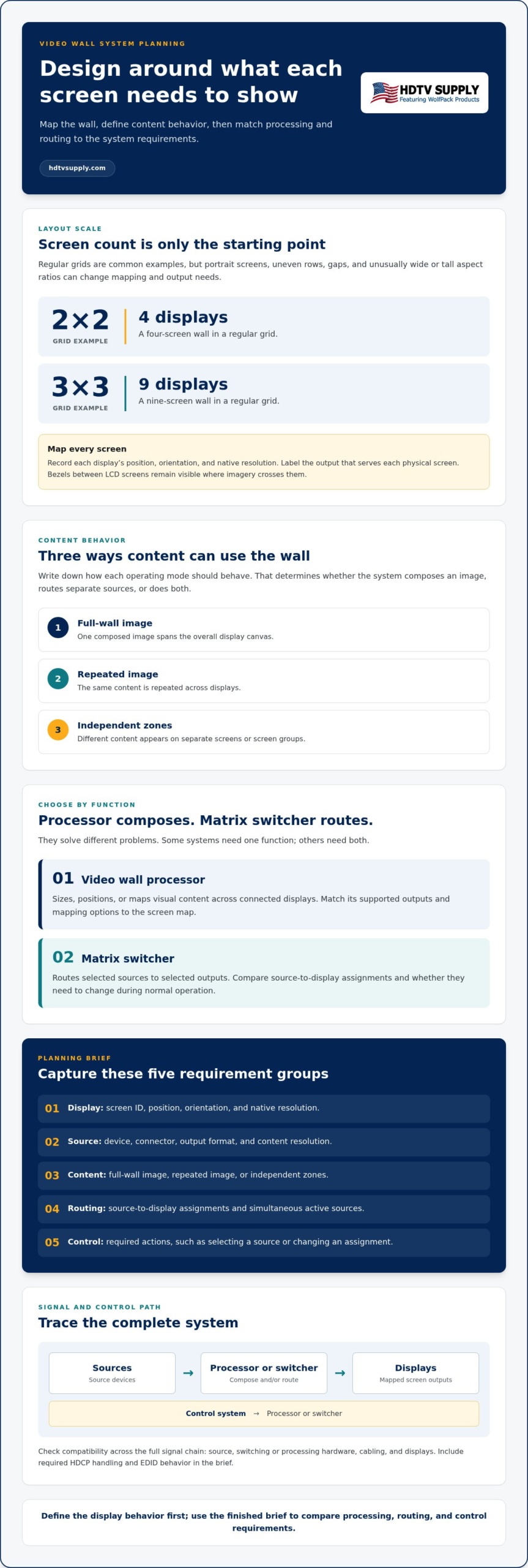
Basic signal and control path:
Sources → Processor or switcher → Displays
Control system → Processor or switcher
This is a planning model, not a fixed wiring diagram. Some systems combine functions; others use separate processing and routing equipment. Define what the wall must do before deciding which architecture fits.
Which display layouts count as custom video walls?
Regular grids are a common starting point: a 2×2 wall has four displays, and a 3×3 has nine. A configuration doesn’t have to use a uniform grid, though. Portrait-mounted screens, uneven rows, gaps, or an unusually wide or tall aspect ratio can change how content must be mapped and which display outputs are needed.
Document each screen’s position and orientation, then note how the overall canvas should appear. For basic grid setup, see the 2×2 and 3×3 video wall setup guide. For other arrangements, treat the physical screen map as a system requirement, not just a mounting plan.
What should the wall show: one canvas or separate zones?
Decide whether content should span the full wall, repeat across displays, or vary by screen group. A control room overview might combine information into one broad canvas. A retail campaign might show a coordinated image across the wall or separate promotions in different zones. A presentation backdrop might use one large image while other displays show supporting content. For trade show exhibits and presentation environments combining digital video with modular backlit graphics, learn more about Mobile Light Box to see portable visual display options.
Write down the expected behavior for each operating mode. This determines whether the system needs to compose one mapped image, route independent sources to separate outputs, or support both. With the content behavior defined, map the screens, sources, and signal paths.
Map Display Geometry, Sources, and Processing Requirements
Turn the display plan into a technical brief before comparing hardware. Record the number of screens, each display’s orientation and native resolution, and its position in the overall arrangement. Label each output with the physical screen it serves. This gives you a practical basis for checking whether processor outputs and mapping options match the wall.
How do screen count and geometry shape the configuration?
Each display contributes pixels to the wall’s total canvas. In a regular grid, the combined image area depends on how the panels are arranged. Bezels remain visible between LCD screens, interrupting imagery that crosses those boundaries. Portrait screens, offset rows, and other irregular layouts may require processor capabilities suited to custom output arrangements. Don’t assume every processor supports your screen count, orientation, resolution, or mapping pattern.
Capture the layout in a screen map. Label each display and include its resolution, orientation, and position in relation to the other screens. Use this map to compare the physical wall with the processor’s supported outputs and configuration options.
How should you document sources and signal requirements?
Inventory each source device and record its connector, output format, content resolution, and whether it must operate at the same time as other sources. Then map sources to destinations: which input needs to reach which display or display group, and whether those assignments change during normal operation.
Supported formats and resolutions depend on the specific processor and connected equipment. Check specifications across the complete signal chain, including the source, switching or processing hardware, cabling, and displays. Record required HDCP handling and EDID behavior as well. For a deeper explanation, use this HDMI matrix EDID management guide.
Use a requirements table to keep the system details together. Fill in project-specific values instead of relying on assumptions:
Display: Screen ID, position, orientation, native resolution
Source: Device, connector, output format, content resolution
Content: Full-wall image, repeated image, or independent zones
Routing: Source-to-display assignments and simultaneous active sources
Control: Required actions, such as selecting a source or changing an assignment
This brief helps expose mismatches before equipment selection. Use it to compare processing and routing requirements with HDTV Supply’s professional AV hardware, including HDMI video wall processors and modular matrix switchers.
Video Wall Processor vs. Matrix Switcher: Compare the Right Architecture
A processor and a matrix switcher solve different problems. A processor arranges visual content across displays; a matrix switcher routes sources to selected outputs. For custom video wall configurations, choose based on the system’s required functions, not simply the number of screens. Some designs need one function; others need both.
| Planning question | Video wall processor | Matrix switcher |
|---|---|---|
| Primary job | Compose, scale, crop, or map content across a wall. | Route selected input sources to chosen outputs. |
| Best fit | A composed image or defined layout spanning multiple displays. | Flexible source selection across displays or other destinations. |
| Key checks | Input formats, output count, mapping options, and control method. | Input and output counts, signal compatibility, and routing control. |
When is a video wall processor the better fit?
Choose a processor when the wall needs to act as one canvas, with content scaled, cropped, or mapped across multiple screens. Confirm that its input formats and output count match the system and that its layout options support the intended screen arrangement. Consider how operators will select or adjust layouts, too. HDTV Supply offers HDMI video wall processors. See this video wall processor guide for processing fundamentals.
When does a matrix switcher belong in the design?
A matrix switcher fits systems where users need to choose which source appears on which destination. For example, an operator might route different source devices to separate displays, then change those assignments as needs shift. A switcher handles routing, but that doesn’t automatically give it dedicated wall-processing functions, such as composing and mapping a continuous image across screens. See the modular HDMI matrix switcher guide for more on routing architecture.
Some systems combine both functions: a processor creates the wall image, while a matrix switcher selects the sources feeding the processor or other displays. Use a hybrid design when the requirements call for both tasks and the selected equipment supports the necessary signal path. HDTV Supply’s HDMI video wall processors and WolfPack Modular Matrix Switchers serve these distinct hardware roles. Compare video wall processing and matrix switching hardware with the completed system requirements.
Plan a Custom Video Wall Configuration in Five Steps
A clear workflow turns a display concept into a system design you can evaluate before ordering hardware. For custom video wall configurations, give each step a concrete output and keep assumptions separate from validated requirements.
- Define viewing goals. Specify what viewers need to see and whether content spans the wall, repeats, or appears in separate zones. Planning artifact: a content and viewing brief.
- Document the display layout. Record display quantity, orientation, native resolution, physical positions, and content zones. Include expected operating hours and how users will control the system. Planning artifact: a labeled screen map.
- Inventory sources. List each source device, connector type, output format, and the content it supplies. Note switching needs and whether multiple sources must appear simultaneously. Planning artifact: an input-output schedule.
- Select the architecture. Decide whether the design needs image composition across screens, source routing to destinations, or both. Planning artifact: a signal-flow diagram showing sources, processing or switching, displays, and control.
- Verify compatibility. Check the specifications of every device and connection against the intended signal path. Planning artifact: a compatibility checklist with validated items and open questions.
What belongs in a video wall configuration brief?
Bring the screen map and input-output schedule together with the content zones, operating hours, and control expectations. Add source connector types, switching behavior, and any requirement to show multiple sources at once. Mark each item as confirmed or to validate. This distinction keeps assumptions, such as a source’s output format or a cable path’s capability, from becoming unnoticed design constraints.
How can you reduce compatibility problems before purchase?
Trace every signal from source through processing and distribution to its intended display. At each point, verify supported resolution and signal formats, HDCP behavior, EDID handling, and the cable or distribution path. One unsupported link can affect the entire route, so validate the chain as a system rather than as a set of isolated devices. HDTV Supply’s technical support can help assess professional AV equipment selections against your documented requirements.
Before finalizing the equipment list, review the system diagram and flag project-specific specifications that still need technical validation. Then use the brief to compare suitable HDMI video wall processors and modular matrix switchers. Explore video wall processors and matrix switchers that fit your planned signal flow.
Choose Processing and Routing Hardware for the Final Design
Use the completed requirements brief to narrow the hardware category before comparing individual products. It should capture the display layout and native resolutions, content behavior, source and destination assignments, signal paths, and control needs. This gives you a practical reference for matching custom video wall configurations to processing and routing equipment without choosing by screen count alone.
Match the hardware category to the wall behavior
Start with the system’s primary job. If the wall needs one composed image mapped across multiple displays, consider an HDMI video wall processor. If users need to route different sources to selected screens or other destinations, consider a matrix switcher. A design that requires both composition and flexible routing may need both functions, provided the selected equipment supports the complete signal path.
| Requirement | Relevant hardware role | What to compare |
|---|---|---|
| Compose or map a canvas across displays | HDMI video wall processor | Input formats, output count, resolution support, layout options, and control |
| Route sources among displays or destinations | Matrix switcher | Input and output requirements, supported formats, and routing control |
| Compose the wall and select sources for it | Processor and matrix switcher, if supported by the design | Compatibility and signal handling at every connection in the chain |
Capabilities vary by product. Compare the documented input, output, resolution, signal-format, and control specifications with the requirements brief. Don’t assume a category label guarantees the output mapping or routing behavior your design needs.
HDTV Supply offers HDMI video wall processors for display-mapping needs and WolfPack Modular Matrix Switchers for modular source-routing requirements. Use the brief to evaluate relevant product details and technical support options as you refine the equipment selection.
What is the next step after planning a custom configuration?
Before purchasing, complete this final check:
- Display layout and resolutions are documented.
- Content behavior and signal paths are mapped.
- Compatibility has been checked across sources, processing, distribution, and displays.
- The hardware category matches the wall’s composition and routing requirements.
Once the design is aligned, integrators and AV buyers can explore HDTV Supply’s professional video wall processing and matrix-switching hardware through its online storefront. Technical support is also available for professional AV equipment questions.
Move from Configuration Plan to Hardware Selection
A reliable wall starts with a clear system plan. Document the display arrangement, content behavior, source-to-screen routes, and control needs before matching equipment. Then verify that the complete signal chain supports the required formats and resolutions.
Processors and matrix switchers have distinct roles. HDMI video wall processors handle display mapping and composed-wall requirements, while WolfPack Modular Matrix Switchers support modular source-routing designs. The right choice for custom video wall configurations depends on the job each device must perform and the specifications of the full system.
HDTV Supply provides professional AV hardware and technical support to customers worldwide. Explore professional video wall processing hardware and compare the available categories with your documented requirements.
With the design grounded in a practical plan, you can move forward with a system suited to the way your wall needs to work.
Frequently Asked Questions
What is a custom video wall configuration?
A custom video wall configuration is a system plan that matches a display arrangement with its content, sources, processing, routing, and control needs. It may use a regular grid or a less conventional layout, depending on the space and intended viewing experience. The plan defines whether content spans the full wall, appears in separate zones, or changes between sources. Select hardware after documenting requirements and checking each device’s specifications.
How do I choose a video wall processor for a custom layout?
Start by documenting the number, orientation, and resolution of the displays, then define how content should appear across them. List the required sources, signal formats, output mapping, and control method. Compare these needs with each processor’s specifications, including supported layouts and formats. Don’t assume a processor supports every screen arrangement. Validate the entire signal chain, from source through processing to display, before selecting equipment.
Can a matrix switcher control a video wall?
A matrix switcher can route sources to selected outputs, making it useful in some video wall systems. Routing and wall processing are different functions, though. A switcher doesn’t necessarily compose or map a single image across multiple displays. First identify whether the design requires source routing, image composition, or both. Then verify that the selected devices support the required signal formats and work together across the complete signal path.
What information do I need before configuring a video wall?
Record the display count, orientation, resolution, physical layout, and intended content zones. List source devices, their connector and signal requirements, and which sources need to appear simultaneously. Include how users will change content, plus any relevant HDCP or EDID considerations. A labeled screen map, input-output schedule, and simple system diagram make the design easier to review and help identify compatibility questions before you select equipment.
Can a video wall show different content on different screens?
Yes, a video wall may show one image across the full canvas, duplicate content, or display separate content in defined zones. The available behavior depends on the processor and system architecture. Define the screen groups, source assignments, and number of sources that need to be active at once. Then check the equipment specifications to confirm that the intended output mapping and content behavior are supported.
Do I need both a video wall processor and an HDMI matrix switcher?
Not always. A processor may suit a system whose main task is arranging content across displays, while a matrix switcher may be useful when sources need routing among multiple screens or destinations. Some designs require both functions, but the signal path must support that arrangement. Map the content behavior and source-to-display routes first, then compare the required capabilities with each device’s specifications.
How do I prevent compatibility issues in a video wall system?
Trace each signal from its source through switching, processing, and distribution to the intended display. Check supported resolutions, signal formats, connectors, HDCP behavior, and EDID requirements across every device. Include the planned cable and distribution paths in the review. Don’t rely on one component’s headline resolution as proof of system compatibility. Confirm that the full chain supports the required signal and content behavior before purchase.
Leave a Reply
Want to join the discussion?Feel free to contribute!