
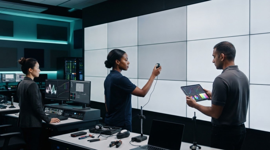
How to Calibrate a Video Wall for the Best Picture
What if the panel that looks too bright isn’t the one that needs adjusting? Brightness differences, color shifts, and uneven tones can come from different settings, and adjusting by eye may make the whole image less consistent. If you’re learning how to calibrate a video wall for best picture, follow a repeatable measurement sequence, then review the wall as one display.
Visible differences between panels are distracting, and it isn’t always clear which adjustment to make first. A reliable workflow helps you match brightness, white point, and tonal response instead of chasing one mismatch at a time. It also gives you a consistent way to reassess the picture after replacing a panel or module.
This guide covers preparation, measurement tools, adjustment order, and final verification. You’ll learn how to compare panels with consistent test patterns and record results for future checks. It also explains where a video wall processor fits: it manages signal layout and display mapping, while calibration requires measuring and adjusting the display itself.
Key Takeaways
- Understand how luminance, white point, and tonal response contribute to a uniform-looking wall.
- Choose a calibration method that suits the display type, available measurement tools, and required precision.
- Learn how to calibrate a video wall for best picture by working through stabilization, measurement, adjustment, and validation in order.
- Separate source, processor, and display settings so adjustments address the right part of the signal chain.
- Record targets, measurement locations, and settings to make future checks after service or module replacement more repeatable.
Why calibrate a video wall for a consistent picture?
A video wall combines multiple displays or LED modules into one visual canvas. Each section needs to reproduce the image in a similar way, or differences between sections can distract from the content. Video wall technology and calibration go hand in hand: the wall’s separate display surfaces need to present a coherent image, not just receive the same source signal.
Video wall calibration is the measured adjustment of each display or LED module to shared picture targets so the wall appears visually consistent across its full surface. Those targets cover more than brightness. They also define the neutral appearance of white and how smoothly each display renders tones from dark to light.
Calibration is different from signal routing and display mapping. Routing determines which source reaches which output; mapping arranges the image across the wall. A video wall processor can handle signal layout and display mapping, but those functions don’t automatically make individual displays match. Raising a brightness control alone is not full calibration: it won’t necessarily correct a color tint or mismatch in tonal response. Keep these functions separate when considering how to calibrate a video wall for best picture, so display adjustments don’t mask a signal-chain issue.
What makes a video wall look like a patchwork?
Review the wall from the normal viewing distance, not only one panel up close. One area may look brighter, another slightly green or blue, and a third may render shadows or highlights differently. Differences often stand out on uniform content, such as a gray background, pale sky, or large white slide. The eye compares neighboring areas, making small variations noticeable across a broad canvas.
Individual displays can vary, and their operating history may affect how they perform over time. Temperature can also influence output, so a wall that looks uniform immediately after startup may look different once it has warmed up. Physical seams, gaps, and misaligned surfaces are separate issues. Calibration can align picture characteristics, but it can’t correct the wall’s physical assembly.
Which picture characteristics should match?
Start with three shared targets. Luminance is the light output perceived as display brightness. White point describes the color appearance of white; when it differs between displays, neutral content can look tinted in one section. Gamma or EOTF describes how input signal levels translate into displayed tones. A mismatch can make midtones look lighter or darker, even when peak brightness appears similar.
- Luminance: Match the wall’s intended brightness rather than judging each display in isolation.
- White point: Aim for a consistent neutral white across viewing areas.
- Tonal response: Compare dark, middle, and bright levels so gradients and image detail transition evenly.
Set targets according to the content, display technology, and viewing conditions. A control room showing detailed feeds may need a different practical balance from a presentation wall in a brightly lit space. The goal is a consistent, usable image for the intended environment, not an arbitrary setting applied to every installation.
How LCD and LED video wall calibration differ
LCD video walls use separate panels, while direct-view LED walls build the image from modules assembled into cabinets. Both need consistent brightness and color, but their adjustment points differ. LCD controls are often found in each display’s picture settings. LED calibration may involve module or cabinet controls, as well as sender and controller processing. Treating the workflows as interchangeable can lead to adjustments in the wrong part of the system.
A video wall processor handles signal layout and display mapping, not necessarily calibration of the display surface. Keep those functions distinct as you plan how to calibrate a video wall for best picture. The video wall processor guide explains the processor’s role in the wider signal chain.
Calibrating an LCD video wall
Start by matching picture modes and available controls across panels. Measure luminance, white point, and grayscale, then adjust the settings exposed by each display. Even identical models with identical settings can look different because panel output varies or changes with use. Use measurement results, not menu values alone, to determine whether neighboring panels actually match.
Calibrating an LED video wall
For LED, check module and cabinet uniformity, then account for sender settings, mapping, and controller processing. A colorimeter or spectroradiometer can measure output at selected positions. Depending on the system and method, camera-based workflows can capture broader areas. Set targets to suit the project’s content, viewing conditions, and system capabilities instead of assuming one target fits every LED wall.
Use this comparison to identify where measurement and adjustment belong. The exact controls depend on the display and signal chain.
| Technology | Measurement focus | Control point | Verification step |
|---|---|---|---|
| LCD panels | Panel luminance, white point, grayscale | Display picture controls | Compare panels with the same test patterns |
| LED modules | Module and cabinet output uniformity | Controller, sender, or supported module controls | Review mapped output across cabinets and the full wall |
For LCD, make display-native adjustments where available. Avoid using processor output controls to compensate for a panel-specific mismatch. For LED, confirm mapping and processing before adjusting uniformity, so a configuration issue isn’t mistaken for a module color difference. A colorimeter or spectroradiometer provides point measurements. A camera-based approach can cover a broader area, but its suitability depends on the workflow.
Keep the sequence specific to the technology: stabilize and assess the wall, confirm the signal path, measure, adjust at the appropriate control point, then verify the complete image. If you’re selecting signal-processing hardware for a wall, explore HDMI video wall processors as part of planning the system.
Which video wall calibration method should you use?
Choose a method based on the wall’s scale, the consistency required, and how results will be evaluated. A visual check can reveal an obvious mismatch, but it won’t provide measured values for comparison. Instrument-based and camera workflows offer more repeatable evidence, while controller tools can apply adjustments when the system supports them.
Choose a measurement method that matches the required repeatability and project acceptance criteria, then use the same setup to verify the result.
- Visual matching: Quick and accessible for preliminary checks or non-critical displays. It relies on perception, so it is difficult to reproduce precisely.
- Colorimeter or spectroradiometer: Measures light and color at defined points. Useful for repeatable comparisons and documented acceptance, though results depend on correct setup and consistent measurement locations.
- Camera-based workflow: Captures a broader area, which can help assess uniformity across a large wall. Results depend on the camera, capture conditions, and workflow, so this method isn’t interchangeable with a point measurement.
- Controller tools: May provide supported adjustment functions within an LED system. They can streamline configuration, but don’t replace independent verification of the displayed image.
When is visual matching sufficient?
Use visual inspection as a first pass or when formal measurement isn’t required. Display neutral test images, such as gray or white fields, and view them from the intended audience position. Keep room lighting and viewing conditions steady. Your eyes adapt to brightness and color, while ambient light can shift perceived neutrality. That makes visual matching subjective and less repeatable, especially across a large or critical installation.
When should you measure with instruments?
Use measured luminance and color data when adjustments need to be repeated, compared over time, or assessed against project acceptance criteria. A contact instrument measures specific locations on the display; a camera captures a wider area according to its workflow. Controller-assisted adjustment is a separate control method, not a measurement method. It changes supported system settings, while instruments or camera capture provide evidence about the result.
For a useful record, note the instrument or camera, measurement setup, target values, measurement locations, and results. Keep these details consistent for later checks. For example, if visual inspection reveals a tint in one corner, record its location and measure it alongside nearby areas instead of relying on memory or adjusting the whole wall by eye.
For how to calibrate a video wall for best picture, a practical workflow often combines methods: inspect the full image visually, measure key locations, adjust through the appropriate display or controller controls, then verify again. The balance depends on the project’s precision needs and the system’s capabilities. If you’re planning signal distribution alongside calibration, explore HDMI video wall processors as part of the system design.

How to calibrate a video wall: a repeatable step-by-step process
A reliable calibration sequence keeps signal-chain troubleshooting separate from picture adjustment. First confirm that the source delivers the intended signal consistently. Then check processor configuration and display settings separately. This prevents a source or mapping problem from being “fixed” with display controls, which could create new mismatches elsewhere on the wall.
Prepare the wall and establish calibration targets
Before measuring, let the displays reach stable operating conditions according to the manufacturer’s guidance. Use the same signal format and picture mode throughout the wall, and choose a consistent measurement position for each panel or module. Define project-specific luminance, white-point, and tonal targets based on the content and viewing environment. Record the targets before making changes so you can check the final result against them.
- Stabilize the displays. Power and operate the wall as directed by its manufacturer before taking readings. Keep room lighting and other measurement conditions consistent during the session.
- Set the signal path. Confirm the source format, routing, processor configuration, and display mapping. Check that each output receives the intended signal. For systems using an HDMI matrix, HDMI matrix EDID management guidance can help explain how consistent format negotiation supports reliable signal delivery.
- Define targets and locations. Choose the project’s picture targets, then mark repeatable measurement positions across the wall. Include displays or modules at the edges and center rather than relying on a single representative location.
Measure, adjust, and verify the result
Measure before making changes. Work through the wall systematically, and keep a clear record of which settings belong to the source, processor, and individual displays or LED controller. Recheck after each meaningful adjustment. This helps you see whether a change improved consistency or introduced another mismatch.
- Measure across the wall. Take readings at the planned positions and compare luminance, white point, and tonal response. Include neighboring panels or modules, since a single central reading can miss local differences.
- Adjust the relevant controls. Correct source-level issues at the source, mapping or routing issues in the processor, and display-output differences using the appropriate display or controller controls. Change one category at a time, then repeat the affected measurements.
- Validate and document. Check neutral grays for tint or uneven levels, color content for visible shifts, and real program material for a natural overall image. Save final settings, target values, measurement positions, and before-and-after results so future checks use the same reference.
Finish by viewing the entire wall from its normal audience position. Measurements provide a repeatable record; a full-wall visual review confirms that the image works as a unified canvas. If you’re selecting signal-processing hardware for a video wall, explore HDMI video wall processors for your system design.
Keep video wall picture quality consistent after calibration
Calibration results provide a reference point, not a permanent guarantee of a uniform image. A replacement panel or LED module can differ from surrounding displays, while service work or processing changes may alter the signal reaching the wall. Even without hardware changes, temperature, operating conditions, and room lighting can affect how consistent the image appears.
Keep a calibration record that lets you compare the wall with its previous state. Save target values, measurement locations, display and processing settings, instrument setup, and before-and-after readings. Note the date and any hardware or signal-chain changes. This helps you determine whether a mismatch is new, localized, or part of a broader change.
What should trigger a calibration check?
Use a visual review to catch obvious changes during routine operation. Instrument-based recalibration is more appropriate when measurements show a persistent mismatch or project requirements call for documented verification. Set review intervals according to operating conditions and acceptance requirements rather than applying a universal schedule.
- Check after service or replacement: Reassess the affected area and adjacent displays after a panel or module is replaced.
- Review after system changes: Recheck when processing, routing, mapping, or display settings have changed.
- Investigate persistent differences: If a visible tint or brightness mismatch remains, compare readings with the saved baseline before making broad adjustments.
- Account for the room: Changes in ambient light or viewing conditions can affect perceived contrast and color. Compare the wall under consistent conditions before deciding that the display itself has drifted.
A quick visual check helps identify where to look, but it doesn’t replace measurement when repeatable results or formal acceptance matter. Use the recorded measurement positions and targets for a like-for-like comparison. If only one section looks different, measure that area and its neighbors before adjusting the whole wall.
Plan the AV signal chain around consistent output
When the picture changes unexpectedly, trace the signal path from source format through switching and processing to the display inputs. Confirm that the source delivers the expected format and each stage routes it as intended. EDID and signal-format mismatches can affect input compatibility or the format passed through the chain. They don’t directly calibrate color or correct a panel’s luminance.
An HDMI video wall processor is part of system design for signal layout and display mapping. It can help organize how sources reach the wall, but it shouldn’t be treated as a calibration solution. Keep signal configuration and display calibration as separate diagnostic tasks. For system planning, review HDMI video wall processors as a relevant hardware category.
For consistent maintenance, preserve the baseline, inspect after meaningful changes, and measure when a visual check identifies a lasting difference. That record turns how to calibrate a video wall for best picture into a repeatable practice rather than a one-time adjustment.
Make your next calibration easier to repeat
Turn your next picture check into a useful baseline. Save the settings and measurement notes in a format your team can update after a display change or service visit. That record helps you compare results over time and make the next decision more precisely: adjust a display, investigate the signal path, or review the wall’s processing configuration.
As you plan how to calibrate a video wall for best picture, consider the signal-processing design alongside the calibration workflow. HDTV Supply sells HDMI video wall processors and provides product assistance to installers and integrators worldwide. Its catalog includes more than 12,000 professional AV products for a range of system-planning needs.
Ready to evaluate processing hardware for your setup? Explore HDMI video wall processors and take the next step toward a consistent, well-managed display system.
Frequently Asked Questions
How often should you recalibrate a video wall?
Recalibrate when measurements or visible changes show that the wall no longer meets its targets, rather than relying on one schedule for every installation. A heavily used wall in a room with changing temperatures may need more frequent checks than a wall in stable conditions. Add brief visual inspections to routine operation, and schedule instrument checks around project acceptance needs, service events, and any recurring drift.
Can you calibrate a video wall with a phone camera?
A phone camera can help you spot obvious differences, but it usually isn’t a dependable measurement instrument for calibration. Automatic exposure, white balance, and image processing can change how the camera records the same test image from one capture to another. Use it only as a quick visual reference. For repeatable color or luminance readings, use a suitable measurement instrument and consistent capture conditions.
What equipment is needed to calibrate a video wall?
For measured calibration, you’ll generally need a colorimeter or spectroradiometer, test patterns, access to the display or controller settings, and a way to record readings. A camera-based workflow may use a camera and associated measurement software instead. The appropriate setup depends on the wall technology and required precision. Before starting, confirm that your measurement tools and patterns support the signals used by the system.
Should every screen in a video wall use the same brightness setting?
Not necessarily. The goal is a consistent measured appearance, not identical menu values. Two displays set to the same brightness level may produce different light output, so their controls might need different values to match. Avoid making one screen excessively bright to compensate for a dimmer neighbor. Compare actual output across the wall and adjust within the displays’ supported operating range.
Why does a video wall look different after replacing a panel or LED module?
A replacement can have different output from surrounding units, particularly if those displays have accumulated different operating histories. Its picture mode, stored settings, or controller configuration may also differ from the unit it replaced. Compare the new component with adjacent areas using the same content and measurement setup. Check its configuration first, then determine whether a targeted adjustment or broader recalibration is needed.
Does a video wall processor calibrate the displays automatically?
No. A video wall processor handles signal functions such as routing, layout, and display mapping; those tasks don’t automatically align the color or brightness of each display. If the wall looks uneven, check that the signal and mapping are correct, then assess display output with visual checks or measurement tools. Keep processor adjustments separate from calibration controls so one issue isn’t masked by changing another part of the system.
What test patterns should you use when calibrating a video wall?
Use several patterns because each reveals a different type of mismatch. A neutral gray field can expose tint or uneven output, while black and near-black patterns reveal differences in shadow detail. A grayscale ramp helps show tonal transitions, and primary-color fields can highlight color discrepancies. A grid or alignment pattern helps check image mapping and geometry, but it doesn’t replace color or luminance measurements.
Can ambient light affect video wall calibration?
Yes. Room lighting can change how bright or neutral the wall appears, and reflections may make one area seem lower in contrast than another. Make comparisons under lighting conditions similar to normal use, and note major changes such as daylight entering through windows or new fixtures being switched on. If room lighting varies throughout the day, assess the display at representative times before changing calibration settings.
Leave a Reply
Want to join the discussion?Feel free to contribute!