
HDMI Matrix Switching for PTZ Camera Displays and Recording
A PTZ camera setup can send the right picture to the wrong screen if routing is planned as an afterthought. An HDMI matrix switcher for PTZ cameras routes camera video to selected displays and recording equipment, provided the connected devices are compatible. HDMI carries the video signal; camera movement control is a separate function.
Choosing the switcher is only one part of getting a reliable setup. You also need to match the camera’s video output to the switcher and plan how each feed will reach local displays and recording devices. This guide explains the connection path, compares hardware and software compatibility, and outlines what affects kit pricing and availability. You’ll see how to assess the system requirements before selecting a matrix configuration for your installation.
Key Takeaways
- Plan display and recording routes around the required destinations so each camera feed reaches the right endpoint.
- Compare kit configurations by their inputs, outputs, signal requirements, and included components, rather than relying on a generic price estimate.
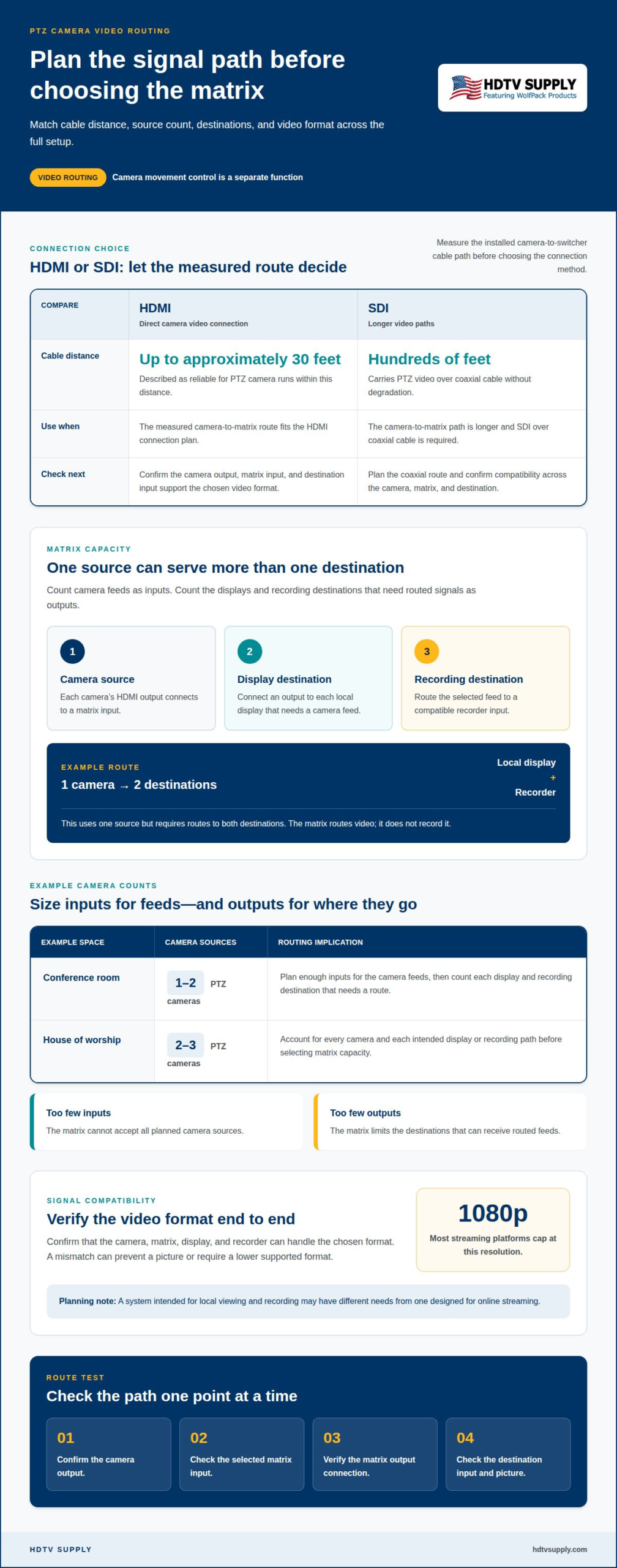
- Use cable distance and connection type to guide the camera-to-switcher path; HDMI is described as reliable for runs up to approximately 30 feet.
- Assess whether hardware or software switching better fits your control workflow, then match the choice to the camera and system’s compatibility needs.
HDMI for local displays and recording
A PTZ camera’s HDMI output can feed a matrix switcher, which routes the video to selected local displays. If the system supports the route, another output can send the feed to a recorder. The switcher manages signal paths; it does not record video. For example, a conference room can route a camera feed to both a confidence monitor and a recording device.
Map each source and destination before connecting equipment. Count the camera feeds, identify every screen and recording input, then assign a route for each use. A matrix with too few inputs cannot accept all planned sources, while insufficient outputs limit the destinations. In a worship space starting with 2-3 PTZ cameras, the routing plan should account for each camera and the intended display or recording paths.
- Camera input: Connect each camera’s HDMI output to a matrix input.
- Display output: Connect an output to each local display that needs a camera feed.
- Recording output: Route the selected feed to a compatible recorder input.
Resolution is another key part of the signal path. Confirm that the camera, matrix, display, and recorder can handle the chosen video format. A mismatch can prevent a picture from appearing or require a lower supported format. Most streaming platforms cap at 1080p, so a system intended for local viewing and recording may have different needs from one designed for online streaming.
Choose the camera feed for each task deliberately. A presenter-facing display may need a different view from the recording feed, depending on the room and production workflow. Test each route by switching between camera inputs and checking the intended screen or recorder. If a display shows no picture, isolate the signal path: confirm the camera output, selected matrix input, output connection, and destination input. Checking one point at a time makes troubleshooting more precise.
Kit prices and availability
A PTZ camera kit’s equipment needs depend on more than the number of cameras. A basic signal path may include cameras, a matrix switcher, displays, and recording inputs. A larger setup may require more destinations or separate control equipment. Compare configurations by function so a lower-cost component does not leave out a required connection.
Build a parts list around a system diagram. Count the camera sources, display destinations, and recording paths, then identify the required switcher inputs and outputs. For example, a room sending camera feeds to both a presenter display and a recorder needs routes to both destinations. The same number of cameras can require different equipment when the number of destinations changes.
- Core equipment: Cameras, matrix switcher, displays, and recording device.
- Signal path: HDMI cables and any required extension method for each connection.
- Control: The interface or control method used to select camera feeds.
- Expansion: Additional routing capacity for planned sources or destinations.
Availability also depends on the chosen configuration. A kit assembled from several components may involve different stock status for each item. Keep the bill of materials specific: list each model’s role, required quantity, and connection type. This helps identify which component affects the complete system and prevents a partial kit from being mistaken for a ready-to-connect setup.
Compare equipment lists on the same basis. Check whether each includes the switcher, cameras, cables, control equipment, and recording hardware. Separate required components from optional additions, such as an extra route to a lobby display. A switcher-only purchase and a full-system package cover different needs. For a practical comparison, tie every item to a source, destination, or control task.
Before ordering, finalize the connection plan and confirm that the selected equipment is compatible as a system. Changes to resolution, routing capacity, or recording destinations can change the required components. A clearly defined equipment list makes it easier to compare configurations and ensure the setup covers the intended installation.
PTZ camera HDMI connectivity
HDMI carries a PTZ camera’s video output to a matrix input. The matrix routes that feed to connected destinations, while camera movement control follows a separate path. To choose an HDMI matrix switcher for PTZ cameras, map the video sources and destinations first, then match the connection method to the physical cable route.
There’s no single input and output count for every setup. Size inputs for camera sources, then outputs for displays and recording destinations that need feeds. A conference room may use 1-2 PTZ cameras; a house of worship may start with 2-3. For facilities coordinating camera feeds within larger property security setups, solutions from Digital-Vision.AI show how video surveillance and monitoring often require additional dedicated display outputs. The output count depends on how many separate destinations need routed signals.
For example, routing one camera to both a display and a recorder uses one source but requires routes to two destinations. Draw each source-to-destination path before selecting a matrix. Include every camera, local screen, and recorder in the diagram. This reveals whether the system needs more inputs, more outputs, or both.
HDMI is described as reliable for PTZ camera cable runs up to approximately 30 feet. For longer paths, SDI can carry PTZ video over coaxial cable for hundreds of feet without degradation. Choose the connection method based on the measured camera-to-switcher distance, rather than assuming every run suits HDMI.
An HDMI matrix switcher for PTZ cameras should support the camera’s output format and connect to compatible destination inputs. A mismatch between the camera, matrix, or display can prevent a usable picture. Choose cables to suit the measured route, and verify video-format compatibility across the full signal path.
- Measure the camera-to-matrix route, including the installed cable path.
- Connect the camera output to a matrix input and select that source.
- Route the source to a display, recorder, or both.
- Test each destination with the intended camera feed and video format.
If the image fails, isolate the signal path one connection at a time. Check the camera output, selected matrix input, cable connection, and destination input. This sequence helps pinpoint whether the problem is at the source, along the route, or at the display.
PTZ camera compatibility with hardware and software switchers
Compatibility depends on the video path, control method, and required destinations. Separate these functions before choosing a switching approach.
Switcher Type Differences
An HDMI switcher selects between sources for an output, while an HDMI matrix routes sources to selected outputs. A video mixer combines or processes sources for a production rather than simply routing feeds. For example, use a matrix when separate displays need different camera views. Compare input and output counts, supported video formats, and whether the production requires video effects.
Choosing a Video Switching Solution
Choose HDMI matrix switching when cameras and destinations use HDMI, and the cable path suits that connection. HDMI is described as reliable for PTZ camera runs up to approximately 30 feet. SDI suits longer coaxial paths, carrying video for hundreds of feet without degradation. HDMI-over-IP can fit systems designed around network distribution; assess network infrastructure and device compatibility before selecting it.
PTZ Control Signal Pass-Through
An HDMI matrix routes video; HDMI itself doesn’t carry VISCA, RS-232, or IP camera-control commands as part of that video signal. PTZ control therefore needs its own compatible control path, such as a serial connection or network connection, depending on the camera and controller. Map video routing and camera movement control separately, then test both functions from the operator position.
Common HDMI Matrix Issues
EDID mismatches can lead to incompatible format negotiation between a PTZ camera, matrix, and display. HDCP restrictions can also affect protected-content paths, depending on the camera and connected devices. For a blank or unstable image, test the source, selected input, cable connection, and destination individually. Check that the video format is compatible across the full path.
Match the switcher to the camera outputs, control method, and routing plan. Explore HDMI matrix switching options for a system built around those requirements.
HDTV Supply
HDTV Supply offers professional AV equipment for PTZ camera systems, including WolfPack HDMI matrix systems. Start by identifying the signal path, required destinations, video format, and separate camera-control method. These details help narrow down the switching and display components that fit the setup.
For camera routing, consider WolfPack Modular Matrix Switchers or WolfPackSecure 4K 60 4:4:4 HDMI Matrix Switchers. WolfPad TV Control Systems address system control, while HDMI Video Wall Processors support video wall display requirements. Each serves a different role, so the system design should guide the selection rather than treating these products as interchangeable.
Contact HDTV Supply to discuss the equipment needs for your PTZ camera display and recording system.
Turn Your System Plan Into a Clear Next Step
Turn a general equipment idea into a concise system specification. Note the camera models, intended display and recording destinations, control method, and required video format. This creates a practical foundation for choosing equipment and identifying any remaining questions before purchase. An HDMI matrix switcher for PTZ cameras should suit the full signal path, not just the camera connection.
HDTV Supply offers WolfPack Modular Matrix Switchers and WolfPad TV Control Systems. Each serves a different AV purpose, so choose the product category that fits the system rather than treating these products as interchangeable.
Bring your system requirements together and take the next step at your own pace. Contact HDTV Supply about your setup. A clear plan makes it easier to move forward with confidence.
Frequently Asked Questions
What is an HDMI matrix switcher and how does it work with PTZ cameras?
An HDMI matrix switcher routes video from connected sources to selected displays or recording equipment. With PTZ cameras, each camera’s HDMI output supplies a video source, and the matrix routes that source to one or more destinations. For example, an operator can send one camera view to a room display and another camera feed to a recorder.
Which HDMI matrix switchers are compatible with PTZ cameras and their resolutions?
Compatibility depends on whether the camera, matrix, display, and recorder support the same video format. Compare the camera’s output options with the matrix’s supported formats and each destination’s input requirements. HDTV Supply offers WolfPackSecure 4K 60 4:4:4 HDMI Matrix Switchers, but the product name alone doesn’t establish compatibility with every camera or resolution. Match specifications across the complete signal path.
How much do HDMI matrix switchers for PTZ camera systems cost in the United States?
System requirements vary with the selected equipment and configuration. Key factors include matrix input and output capacity, video-format requirements, control components, and whether the setup includes cameras, cables, displays, or recording hardware. A switcher-only purchase and a complete system kit cover different scopes. Build the equipment list around the required signal paths to compare equivalent configurations.
How do you connect and configure multiple PTZ cameras with an HDMI matrix switcher?
Connect each camera’s HDMI output to a separate matrix input, then connect matrix outputs to the intended displays or recorder. Use the matrix controls to route each source to its destination, and test every route individually. For example, label camera inputs by location and confirm that the selected feed appears on the intended screen. Set up camera movement control separately from video routing.
Leave a Reply
Want to join the discussion?Feel free to contribute!