

Fiber Optic vs. Ethernet for Video: How to Choose the Right Signal Path
The right answer to fiber optic vs ethernet for video may be both, not either-or. Fiber and Ethernet aren’t competing cable types: Ethernet is a networking standard that can run over copper or fiber, while video may travel as HDMI, HDBaseT, or AV-over-IP. That distinction matters when a signal needs to reach a distant display without compromising format support or reliability.
It’s reasonable to focus on resolution and cable distance first. But the cable alone doesn’t determine what a system can carry. The source, transport method, extenders or network equipment, switching hardware, and display all need to support the required video format. A mismatch anywhere in the chain can lead to an unreliable or incompatible setup.
This guide explains how cable medium, transport method, and video format fit together, then compares where fiber and copper Ethernet make sense based on distance, bandwidth, and installation conditions. You’ll also see how HDBaseT can use category cable and where components such as HDMI matrix switchers and video wall processors fit into a distribution architecture. By the end, you’ll have a clearer framework for choosing a compatible, dependable signal path for your installation.
Key Takeaways
- Choose the transport architecture around your sources, displays, video formats, and control requirements, rather than selecting cable by name alone.
- Compare fiber and copper Ethernet against the installation’s distance, bandwidth needs, electromagnetic interference, PoE requirements, and existing infrastructure.
- Use a system checklist to document resolution, refresh rate, audio, content protection, and the direction each signal must travel.
- For fiber optic vs ethernet for video, remember that performance depends on the complete signal path, including the standard, cable, and connected equipment.
- Match the distribution hardware to the design: matrix switchers route sources to displays, video wall processors manage display layouts, and network-based designs distribute signals over IP.
Fiber Optic vs. Ethernet for Video: What Is Actually Being Compared?
Fiber describes a transmission medium; Ethernet describes a family of wired networking technologies. They aren’t opposites. Ethernet data can travel over copper twisted-pair cabling or over fiber-optic links, while a video system can transport signals directly or distribute them across an IP network. So the useful question behind fiber optic vs ethernet for video is which medium and transport method fit the signal path.
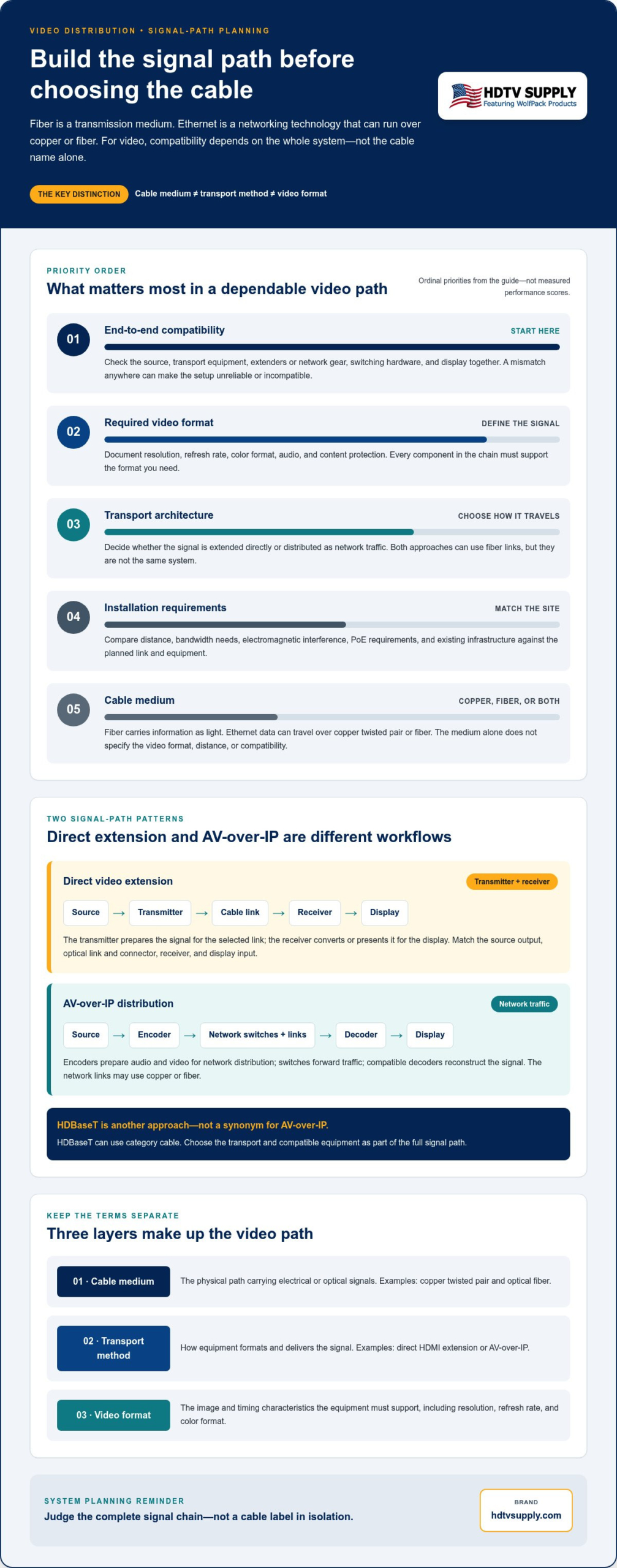
Keep three layers separate: the cable carries a signal, the transport method determines how equipment moves it, and the video format defines what the signal contains. Mixing these terms can lead to an incorrect assumption that an Ethernet cable automatically carries any video format, or that fiber always means networked video.
| Term | What it describes | Video-system example |
|---|---|---|
| Cable medium | The physical path that carries electrical or optical signals | Copper twisted pair or optical fiber |
| Transport method | How the signal is formatted and delivered between devices | Direct HDMI extension or AV-over-IP |
| Video format | The image and timing characteristics the equipment must support | Resolution, refresh rate, and color format |
Fiber-optic video transport is a system that converts or encodes video-related signals for transmission over optical fiber, then delivers them in a usable form at the receiving end. The exact implementation varies, so “video over fiber” alone doesn’t specify a connector, format, distance, or compatibility.
What does fiber optic mean in a video system?
Optical fiber carries information as light through a glass or plastic strand. At a high level, video equipment converts an electrical signal into light for the link and converts it back at the receiver. Optical fiber provides a foundational overview of how this light-based medium transmits information.
Fiber may extend a video signal directly, or serve as the physical link in an IP network. These are different architectures. HDMI-over-fiber and SDI-over-fiber are implementation categories for extending those signal types; AV-over-IP instead distributes video as network traffic, potentially across fiber links.
What does Ethernet mean when distributing video?
Ethernet is a family of wired networking technologies, not a video connector or a synonym for copper cable. A network link can use copper twisted pair or fiber-optic cabling, depending on the equipment and link design. The medium and the networking method are related, but they’re not interchangeable terms.
In AV-over-IP, encoders prepare or packetize audio and video for network distribution. Network switches direct that traffic across connected links, and compatible decoders reconstruct signals for displays or other endpoints. This approach relies on network-capable AV equipment and a compatible signal chain. A direct optical video extender and an AV-over-IP system may both use fiber, but they don’t distribute video in the same way.
How Fiber and Ethernet Carry Video Through an AV System
The cable is only one part of the route. A video signal starts at a source, passes through the equipment that prepares or switches it, crosses one or more links, and arrives at a display. The route may use optical fiber, copper, or both. To assess fiber optic vs ethernet for video, map the devices and signal format at each stage rather than judging the cable in isolation.
In a direct extension, the path is typically source → transmitter → cable → receiver → display. The transmitter prepares the signal for the chosen link, and the receiver converts or presents it in a form the display can accept. In an AV-over-IP design, the path is different: source → encoder → network switches and transport links → decoder → display. The encoder and decoder handle the AV signal, while the network carries its traffic between endpoints.
Direct video over fiber: transmitters, receivers, and optical links
For direct video over fiber, compatible transmitter and receiver hardware convert signals for optical transmission and reception. The source connects to the transmitter, an optical link runs between the endpoints, and the receiver feeds the display. Some systems use a separate transmitter and receiver; others integrate optical components into the cable assembly.
Compatibility depends on the full connection: source output, transmitter, optical connector and link, receiver, and display input. Match the required video format and supported link specifications across those components. Don’t infer supported resolution or operating distance from “fiber” alone. Both depend on the exact product chain and its configuration.
Ethernet video: AV-over-IP and HDBaseT are different approaches
AV-over-IP distributes video as network traffic. An encoder packetizes or otherwise prepares the signal, network switches forward it, and a compatible decoder reconstructs it for the display. Links between network devices may use copper or fiber. Ordinary Ethernet cabling by itself doesn’t create an AV-over-IP system; the endpoints and network equipment must support the intended AV workflow.
HDBaseT is a distinct AV transport technology, not another name for Ethernet or AV-over-IP. It can use category cable to carry AV and related signals between compatible HDBaseT equipment, without turning the connection into a general-purpose network video stream. That distinction helps avoid a common design error: assuming that every device with a category-cable connection can communicate using the same transport method.
Cable choice alone cannot establish video-format compatibility; the source, conversion or encoding equipment, link, receiver, and display must all support the required signal. For network-based video, also account for the switches and links along the route. Cable Matters’ Ethernet Cables for Streaming discusses Ethernet cabling in streaming contexts, but a professional AV-over-IP design still depends on compatible encoders, decoders, and network components.
Once the signal flow is clear, identify where source selection is needed. A professional AV hardware catalog can help integrators connect that requirement to switching and distribution components.
Fiber vs. Ethernet for Video: Compare Distance, Bandwidth, and Site Conditions
Compare the actual link and equipment, not just the words “fiber” and “Ethernet.” Copper Ethernet, Ethernet over fiber, and direct video over fiber have different requirements. In every case, capabilities depend on the specific standard, equipment, cable, and complete signal path. A link’s headline bandwidth or cable category doesn’t guarantee that the entire system supports your target video format.
| Factor | Fiber-optic link | Copper Ethernet |
|---|---|---|
| Distance | Can suit longer links, but supported reach depends on fiber type, transceivers, and endpoint hardware. | Common copper Ethernet channels are typically limited to 100 meters; check the applicable standard and equipment. |
| Bandwidth | Varies by optical standard, transceiver, and video or network equipment. | Varies by Ethernet category, link standard, and connected devices. |
| EMI exposure | Optical transmission is immune to electromagnetic interference and provides electrical isolation across the link. | Copper carries electrical signals and can be affected by electromagnetic interference in some environments. |
| PoE | Fiber itself doesn’t carry PoE power; separate power or copper connections may be needed. | May carry power over Ethernet when the cabling and every relevant device support the required PoE implementation. |
| Infrastructure | Requires compatible optical cabling, terminations, and optical-capable endpoints. | Can use existing structured cabling if it meets the link and application requirements. |
| Hardware | May require optical transceivers, media conversion, or purpose-built video extenders. | May use network switches, AV endpoints, or compatible extenders, depending on the transport method. |
When fiber optic video links make practical sense
Fiber is worth considering for a long video run, a route near equipment that generates electrical noise, or a connection between separate building areas where electrical isolation is useful. It can prevent the optical link itself from creating a conductive electrical path between endpoints. That doesn’t remove the need to plan power, grounding, and protection for the rest of the system.
Plan for compatible fiber termination, transceivers, and endpoint hardware. A purpose-built extender may handle signal conversion, while an optical transceiver may connect network equipment to a fiber link. Match connector type and supported signal requirements, and base reach on the complete product chain rather than the cable alone.
When copper Ethernet or networked video fits the project
Existing structured copper cabling can be practical for suitable distances and compatible equipment. It can also support AV-over-IP, where encoders, network switches, and decoders distribute signals through a configured network. Copper Ethernet may provide PoE to compatible devices, reducing separate power connections at an endpoint, but only when every device and link supports the required implementation.
For networked video, assess switch capacity, network configuration, and traffic management alongside the cable. A link that works for ordinary data isn’t automatically ready for the video system’s bandwidth and traffic pattern. Fiber can also form part of that network, so the decision may involve copper at the endpoints and optical transport between network areas.
Long, electrically noisy routes tend to favor fiber, while suitable existing copper and network-based routing can favor Ethernet; the right choice depends on the full system requirements. Use that as a starting point, then verify distance, format support, power, and infrastructure for each link.
How to Choose a Video Signal Path for Your Installation
Make the decision from the signal requirements outward. A structured workflow helps identify what the system must carry, where it must travel, and which routing or control functions the design needs. Use the same requirements to assess fiber, copper Ethernet, direct video extension, and network-based distribution rather than choosing by cable label alone.
- Inventory sources and displays. List each source, destination, and connection point. Note how many displays need each source, whether different displays show different content, and whether signals need to travel in both directions.
- Document the required formats. Record resolution, refresh rate, chroma format, audio requirements, and content-protection needs for each source-to-display route. Include any processing or switching devices in the path.
- Map every cable run. Measure the route between endpoints, including pathways through racks, ceilings, or between building areas. Record existing cabling and any potential electrical-noise concerns.
- Define topology and control. Decide whether the system needs point-to-point extension, source switching, or distribution to multiple displays. Document centralized control, future expansion, and how equipment will be accessed for service.
- Validate the complete chain. Compare the specifications of the source, transmitters or encoders, intermediate equipment, cable links, receivers or decoders, and displays. Confirm that each component supports the intended format and required signal direction.
Start with the video format and end-to-end requirements
Be specific. “High resolution” isn’t enough to define a compatible signal path. Capture the resolution, refresh rate, chroma format, audio, and content-protection requirements for each route. Then check every device in that route, including processors and switching hardware, against those requirements.
Display identification data can affect what a source outputs when multiple displays have different capabilities. For systems using an HDMI matrix switcher, HDMI matrix switcher EDID management guidance can help explain how source-display communication factors into system planning. Don’t assume a cable category guarantees a format; validate the complete system specifications.
Map distance, topology, and operating conditions
A measured route is more useful than an estimate based on room layout. Include the actual pathway and note whether it crosses electrically noisy areas or building boundaries. Next, match topology to use: a single source and display may need a point-to-point link, while multiple sources and destinations may require switching or one-to-many distribution.
Plan ahead for added displays, centralized control, and equipment access. These needs can change which endpoints, network components, and signal-routing devices belong in the design. For project planning, explore professional AV distribution hardware that aligns with your documented signal path.
Build a Compatible Video Distribution System with the Right AV Hardware
Turn the signal-path decision into a component plan. The right hardware depends on how many sources and displays you’re connecting, whether destinations need independent content, and how signals will travel between endpoints. Fiber, copper Ethernet, and other transport links can each fit within a larger architecture. The goal is a complete system whose components work together, not a cable selected in isolation.
Before specifying equipment, use this checklist to capture the design requirements:
- Sources and destinations: List each source, display, and required routing relationship.
- Signal requirements: Record supported video formats, audio, content protection, and signal direction.
- Transport path: Identify cable type, measured run, endpoints, and any intermediate devices.
- Control: Note how users select sources and whether centralized control is required.
- Expansion: Account for future sources, displays, or changes to display layouts.
Match distribution hardware to the signal path
A matrix switcher belongs in a system that needs to route multiple sources to multiple displays, especially when different displays may need different content. Modular designs can suit systems whose input and output requirements need a configurable approach. For guidance on multi-source, multi-display routing, see the modular HDMI matrix switcher guide.
A video wall processor serves a different role. Use one when multiple displays must operate as a coordinated canvas, with the video arranged across the wall rather than simply routed as separate independent screens. Network-based distribution is another architectural choice: compatible encoders, network components, and decoders distribute signals through the network. It’s appropriate when the system design calls for that routing method and the network can support its requirements.
Coax may also be part of a distribution design. For background on that approach, the professional HDMI modulator guide covers distributing HD video over coax. Each option has its own equipment and compatibility considerations, so compare it against the complete signal path rather than treating it as a simple cable swap.
Confirm compatibility before specifying the complete system
Check supported video formats, connectors, cable types, control methods, and device roles across every stage. A switcher, processor, transmitter, receiver, or display can become the limiting component if its capabilities don’t match the required path. Verify bandwidth and distance limits against current manufacturer documentation for the specific components and configuration. Don’t assume a system inherits the maximum capability of one device or cable.
That end-to-end check brings the fiber optic vs ethernet for video question back to the project: select compatible hardware for the required transport, routing, and display arrangement. Explore professional AV distribution equipment to compare relevant hardware categories, or use HDTV Supply’s technical support for installers and integrators as a resource when planning a compatible system.
Turn Your Signal-Path Plan into a System That’s Ready to Grow
Before specifying hardware, turn your chosen architecture into a clear equipment schedule. Record each source, display, connection, and control requirement, then keep that document current as the system changes. Planning for future sources or display layouts now can make later upgrades more straightforward.
The right fiber optic vs ethernet for video decision is the one that supports your installation today and gives you a practical path forward. Match distribution components to the design, whether that means HDMI matrix switchers for routing or video wall processors for coordinated display layouts.
Explore HDTV Supply’s catalog of more than 12,000 AV products, with technical support for installers and integrators worldwide. Browse professional AV distribution equipment and take the next step toward a compatible, well-planned system.
Frequently Asked Questions
Is fiber optic better than Ethernet for video?
Neither is automatically better; the right choice depends on the link’s job and the equipment at each end. For a run near power equipment, optical fiber avoids electrical interference on the link. For a networked system using suitable existing copper cabling, Ethernet may be the practical fit. In fiber optic vs ethernet for video, compare the required format, distance, power needs, and system topology rather than choosing by medium alone.
Can Ethernet cable carry HDMI video directly?
No, a standard Ethernet cable connected between an HDMI source and display won’t carry HDMI video by itself. The cable needs compatible active equipment, such as an HDMI extender pair or HDBaseT transmitter and receiver. These devices adapt the signal for the link and recover it at the other end. Check the exact video format, audio, content protection, and cable requirements for that extender system before using it.
Can Ethernet run over fiber optic cable?
Yes. Ethernet can operate over fiber when the network devices at both ends support compatible optical interfaces and transceivers, and the fiber link matches their requirements. For example, a switch with an optical port can connect to another compatible switch over fiber, while copper Ethernet serves nearby endpoints. The optical connection remains an Ethernet network link; it doesn’t automatically convert network traffic into a direct HDMI signal.
When should I use fiber optic cable for video?
Consider fiber for a video link that must cross a long route, pass through an electrically noisy area, or connect equipment across building sections where electrical isolation is useful. It can suit a display feed routed away from a central AV rack, provided the endpoints support the required optical link. Before specifying it, account for connector and termination requirements, transceivers or extenders, and compatible equipment at both ends.
Does fiber optic video have less latency than Ethernet?
Not necessarily. The cable medium alone doesn’t determine end-to-end latency. Signal conversion, video compression, network switching, buffering, and display processing can all contribute, and their effect depends on the system design. A direct optical extension may use a different processing path than an AV-over-IP system, but fiber itself doesn’t guarantee lower delay. Compare latency specifications for the complete route under the format and operating mode you plan to use.
Can I use existing Ethernet wiring for a video distribution system?
Possibly, if the wiring condition, cable type, route, and connected equipment meet the system requirements. Existing structured cabling can be used with compatible extenders or networked AV endpoints, but those are different operating methods. Check the cable run and endpoint compatibility, then test a representative source-to-display path with the intended audio and video settings. Don’t assume a cable that supports general network traffic will support every AV application.
What equipment is needed to send video over fiber?
A basic direct link typically needs a compatible transmitter at the source, an optical fiber connection, and a receiver that feeds the display. Depending on the design, optical transceivers or purpose-built extenders may be part of the system. For AV-over-IP over fiber, the signal path also needs compatible encoders, network switches with suitable optical interfaces, and decoders. Select components based on the required format, connectors, and documented link limits.
Leave a Reply
Want to join the discussion?Feel free to contribute!